Software architecture diagrams are a fairly common sight within the teams that I visit around the world. Some are hand-drawn collections of boxes and lines on a whiteboard, others are Microsoft Visio-style block diagrams on a wiki. The one thing that unites most of these diagrams is that they are abstract, out of date and typically don’t reflect the code. It’s 2016 though, why are most software development teams still hand-drawing software architecture diagrams using general purpose diagramming tools such as Visio? Not even the building industry does this! This article explores this topic and presents a simple approach for creating software architecture diagrams using code, so that the resulting diagrams actually reflect the code.
Mention the phrase “software architecture diagram” and most people instantly think about drawing a collection of boxes and lines to somehow represent the structure of their software system. One approach is to hand-draw such diagrams using pen, paper and whiteboard or perhaps a tool like Microsoft Visio. These approaches can work, but the resulting diagrams are simply static pictures that are created by manually drawing boxes and lines on a diagram canvas. You have all of the control over what you draw, and with that control comes the responsibility to ensure the diagram is consistent, accurate and reflective of the reality in the code. Diagrams are static and we can’t ask them any questions. Diagrams are purely visual representations.
The other approach is to create a model of a software system. In contrast to a collection of static diagrams, a model is a non-visual representation or definition of the software system. You can then create a number of visual representations (diagrams) based upon the content of that model. Models are also typically machine-readable, so they can be queried or transformed into other representations too.
The C4 model
I use what I call the “C4 model” to describe and visualise software architecture1. It’s about creating a shared vocabulary that you can use to think about and describe the static structure of a software system using a number of hierarchical building blocks. For example, a software system is made up of one or more containers (web applications, mobile apps, standalone applications, databases, file systems, etc), each of which contains one or more components, which in turn are implemented by one or more classes. This description of the static structure can then be used as a starting point for a collection of simple diagrams, focussing separately on the (system) context, containers, components and classes. The C4 model is compatible with diagramming and modeling approaches.
Modeling tools
Back to modeling then. There are many tools that support this way of working; such as No Magic MagicDraw, Sparx Enterprise Architect, Archi, IBM Rational Software Architect, ArgoUML, etc. There are also modeling tool plugins/extensions for many of the popular IDEs. Essentially they all follow the same principle, by providing you with a way to create and a populate a model. You then use this model to create a number of diagrams, each of which represents a specific view of the model.
As an example, let’s imagine that we want to create a System Context diagram, which is a high- level diagram showing your software system, its users and the other software systems it interacts with. With a diagramming tool, to draw a software system, we need to create a box and put some text inside it. And we need to do this for every software system we want to include on the diagram. With a modeling tool, we create a definition for each software system (e.g. by specifying its name and description) and then use those elements on the diagram by dragging them onto the canvas. If you need to use the same software system across two diagrams, you just drag the element onto the second diagram canvas.
The power of having a model starts to come into play when you need to rename a software system. All you do is rename it in the model and all occurrences of the software system across all diagrams are renamed too. Compare this to a collection of static diagrams where you need to check each diagram and rename any occurrences that you find. This is how a model introduces and improves consistency over a collection of static diagrams.
Modeling tools typically support many different types of models and notations; including the Unified Modeling Language (UML), SysML, ArchiMate and so on. This is great if you want to use these languages, otherwise you’re out of luck. The other aspect you can’t ignore is that you have to create the model, and often it can be a time-consuming task to populate the model with information. If you’re modelling a software system as part of an up-front design exercise, the only real option you have is to use the modeling tool’s user interface to populate the model. This can sometimes require lots of tedious data entry. If you have an existing codebase though, some modeling tools will provide the option to reverse-engineer the code and populate the model for you.
Reverse-engineering and static analysis tools
There are many tools available that will help you reverse-engineer a codebase to create a model. Some of the modeling tools mentioned previously will do this, as will the popular IDEs. In addition, there’s a category of static and dependency analysis tools that will do this too. Examples include Structure101, NDepend, Lattix, Sonargraph, etc. These tools work by scanning your codebase for elements and their dependencies. For an object-oriented programming language such as Java, this usually means creating a model of the code based upon the set of classes, interfaces and packages along with the dependencies between all of these elements. Although the primary purpose of static analysis tools is to provide you information about the quality of your code, most of them also create some sort of architecture diagrams. These tools also resolve the thorny issue of how to keep diagrams up to date as a codebase evolves.
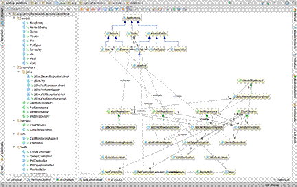
If you’ve ever tried to use a static analysis or modelling to automatically generate meaningful diagrams of your codebase via reverse-engineering though, you will have probably been left frustrated. The resulting diagrams tend to include too much information by default and they usually show you code-level elements rather than those you would expect to see on a software architecture diagram. Here’s what happens if you take a naive approach and generate a UML class diagram for a sample codebase like the “Spring PetClinic” web application2.

It’s worth noting that, thankfully, most static analysis tools won’t show you a single UML class diagram of an entire codebase. Instead they’ll start by showing you the top-level packages/ namespaces and the dependencies between them. Double-click a package to expand it and you’ll be shown the sub-packages and classes that reside within that package, along with the dependencies between them.
Although some static analysis tools claim to generate “architecture diagrams”, the diagrams they actually create are still very code focussed. Like us browsing a codebase, these tools see classes and interfaces in packages/namespaces when reverse-engineering code. Some tools can be given rules to recognise architectural constructs (e.g. components or layers) but this isn’t typically the default out-of-the-box experience. In essence, these diagramming tools suffer from what George Fairbanks calls the “model-code gap”3, where our mental model of a software system differs from that used by the code. While we often describe software using terms such as component and layer, programming languages like Java don’t have “component” and “layer” keywords. Instead, there’s a mapping from the language constructs (e.g. class, interface and package) to components and layers.
Auto-generating the software architecture model
??Ultimately, I’d like to auto-generate as much of the software architecture model as possible from the code, but this isn’t currently realistic because most codebases don’t include enough information about the software architecture to be able to do this effectively. This is true both at the “big picture” level (context and containers) and the lower level (components). One solution to this problem is to enrich the information that we can get from the code, with that which we can’t get from the code.
There have been a number of attempts to create “Architecture Definition Languages” (ADLs)4 that can be used to formally define the architecture of a software system, although my anecdotal experience suggests these are rarely used in real-world projects. There are a number of reasons for this, ranging from typical real-world time and budget pressures through to the lack of perceived benefit from creating an academic description of a software system that isn’t reflective of the source code.
Extract and supplement
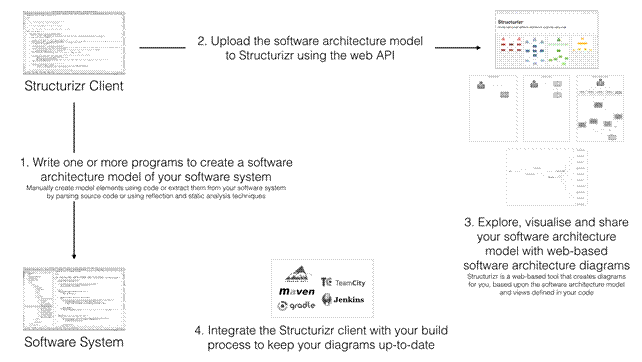
In my own attempt to solve this problem, I’ve created “Structurizr”5 to combine the benefits you get from creating a model using text and having it kept up to date using static analysis techniques. Put simply, it’s a way to create a software architecture model as code, and then have that model visualised by some simple tooling. The goal of Structurizr is to allow people to create simple, versionable, up-to-date and scalable software architecture models. 
Structurizr is a tool of two halves. First is an open source library called “Structurizr for Java”6 that can be used to create a software architecture model using code. It’s an architecture description language based upon the C4 model, implemented in Java. It’s essentially a domain specific language that you can use to describe the static structure of a software system, with Java classes that represent people, software systems, containers and components. In a typical usage scenario, the people, software systems and containers are created manually using code, whereas the components are extracted automatically from a codebase using static analysis and reflection techniques.
To do this, you need to understand what a “component” means in the context of your codebase. With a Spring MVC application, for example, perhaps this is as simple as finding all of the Java classes that are annotated using @Controller, @Service and @Repository. The Structurizr for Java library includes a ComponentFinder class, and there are a number of different implementation strategies that you can plug in and extend to help you extract components from your own codebase. Example strategies for identifying and extracting components include finding classes annotated with a given set of annotations (e.g. Spring, Java EE, etc), naming conventions (e.g. find all classes where the name ends with “Service”) and so on. In addition to finding components, the ComponentFinder will also work out the dependencies between those components. A full code example that describes the static structure of the Spring PetClinic web application can be found in the Structurizr for Java GitHub repository7.
Visualising the software architecture model
The open source Structurizr for Java library allows you to create an in-memory representation of the software architecture model, in this case as a collection of Java objects. It also includes a way to export this model to a number of external representations, including a JSON document, which can then be imported into some tooling that is able to visualise it.
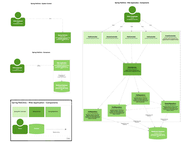
Structurizr.com is the other half of the story. It’s a web application that takes a software architecture model (via a web API) and provides a way to visualise it. Aside from changing the colour, size and position of the boxes, the graphical representation is relatively fixed. This in turn frees you up from messing around with creating static diagrams in drawing tools. As a disclaimer, Structurizr is a commercial product with free and paid plans, but you’re not limited to using it because you can write code to export the model created by the open source Structurizr for Java library to other formats too (e.g. Graphviz, XML Interchange for UML, etc). The result of visualising the Spring PetClinic model with Structurizr, after moving the boxes around, is something like the following.

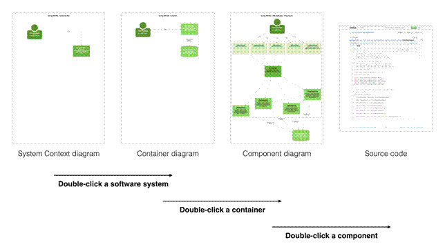
The live version of the diagrams can be found online8 and they allow you to double-click a component on the component diagram in order to navigate directly to the Spring PetClinic code that is hosted on GitHub. This links the software architecture diagrams with the code, essentially creating a set of maps of your software.

Software architecture as code opens opportunities
Having the software architecture model as code opens a number of opportunities for creating the model (e.g. extracting components automatically from a codebase) and communicating it (e.g. you can slice and dice the model to produce a number of different views as necessary). For example, showing all components for a large system will result in a very cluttered diagram. Instead, you can simply write some code to programmatically create a number of smaller, simpler diagrams, perhaps one per vertical slice, web controller, user story, etc. You can also opt to include or exclude any elements as necessary. For example, I typically exclude logging components because they tend to be used by every other component and serve no purpose other than to clutter the diagram.
Since the software architecture models are created using code, they are also versionable alongside your codebase and can be integrated with your automated build system to keep your models up to date. This provides accurate, up-to-date, living software architecture diagrams that actually reflect the code. As an industry, I think we still have a long way to go but, in time, I hope that the thought of using a drawing tool like Microsoft Visio for creating software architecture diagrams will seem ridiculous.
References
1. See “The Art of Visualising Software Architecture” (available for free) for more information about the C4 model. https://leanpub.com/visualising-software-architecture
2. https://github.com/spring-projects/spring-petclinic
3. See “Just Enough Software Architecture” by George Fairbanks for a discussion of the model- code gap and why it exists. http://rhinoresearch.com/book/
4. See https://en.wikipedia.org/wiki/Architecture_description_language for more information.
5. https://www.structurizr.com
6. https://github.com/structurizr/java
7. https://github.com/structurizr/java/blob/master/docs/spring-petclinic.md
8. https://www.structurizr.com/public/1
 NLJUG – Nederlandse Java User Group NLJUG – de Nederlandse Java User Group – is opgericht in 2003. De NLJUG verenigt software ontwikkelaars, architecten, ICT managers, studenten, new media developers en haar businesspartners met algemene interesse in alle aspecten van Java Technology.